One of the key questions in any design is what it will be made off. The “right” material for the job is determined by having the “right” combination of properties. And to determine a material’s properties you must test it! There are myriad material properties and even more types of tests, and our Materials Science module delves into this. Three of the experiments featured in that module are testing aspects of how strong a material is.
In this post, we provide plans for the testing jigs needed to perform these experiments, along with a discussion of how to construct and use them. These jigs are designed to be simple to use, even for young children; you couldn’t use them to obtain accurate measurements of “true” material properties, but are perfect for making relative comparisons between materials. (The research- and industry-grade devices that can make these measurements are neither kid- nor budget-friendly!)
We wanted these designs to be inexpensive, durable, able to be disassembled, and require minimal tools and skill to construct. Building all three only requires a saw (for simple 90° cuts), a drill, a screwdriver, and a ruler/tape measure. All the wood parts are made from 1×2 furring strips, which are basically the cheapest wood you can buy at any home improvement store, yet will still withstand clumsy young hands. You may notice we’ve not listed specific screw dimensions in the blueprints; this is because it’s honestly not critical to these designs. Use whatever wood screws you can find for cheap, just make sure they’re not so long that the sharp tips poke out the back (ouch!). Again, these are readily available at any home improvement store.
NOTE: These designs and their measurements are all just one possible way of constructing such a jig. They are not the only way. Use them as guidelines; these are what’s worked for us, so far. Don’t be afraid to tailor them to fit your needs and materials. If you have wood of other sizes lying around, or maybe lots of nuts-and-bolts rather than screws, don’t hesitate to adjust the design to your needs. The photos we’ve included are from our initial versions, indeed constructed from scrap wood and excess screws. They did the job! In each jig’s section, we’ll note some alternative materials and approaches, but there are always more to find. Let us know what you come up with!
Three-Point Bend Testing
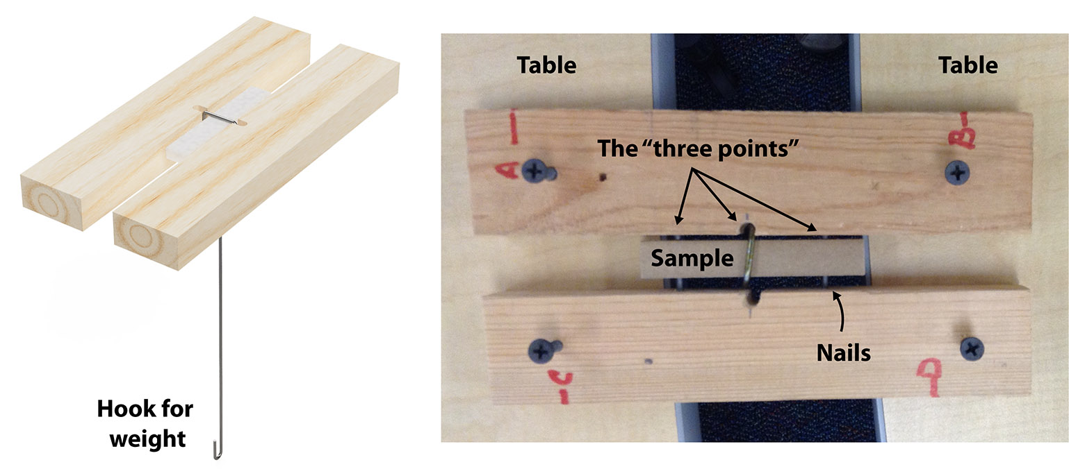
This is the simplest of the jigs, built to perform a test similar to what’s called a three-point bend test (or three-point flexural test). In those tests, the material is supported at two points from underneath (in a manner that allows the material to slide as it bends), and a weight slowly pushes down in the center (the third point). On a properly calibrated machine, with carefully controlled sample geometries, strain rates, etc, this test can be used to determine a material’s flexural modulus (how it resists bending) and flexural strength/modulus of rupture (how much stress the material can take before breaking in a flexural test.
This simplified version won’t yield these exact values, but it is perfect for relative comparisons between a variety of materials while being dirt-cheap and easy for young kids to use! Instead of pushing down from the top, a wire hook loops around the sample’s middle; a weight hanging from the end of this hook pulls down on the wire loop, providing the same effect. By measuring the amount of weight that could be applied before the sample broke, students gain a quantitative comparison of how much various materials resist bending. The manner in which the samples failed also tells you important information about it: Did it suddenly snap without bending much? Did it bend so much it eventually slipped through without breaking?
Supplies
- Two 8 inch pieces of 1×2 wood (long enough to bridge the gap between tables)
- Two Finishing nails (at least ~2 inches long)
- Metal coat hanger or other piece of heavy wire
- Bucket(s) or bag(s) for holding weight
Construction
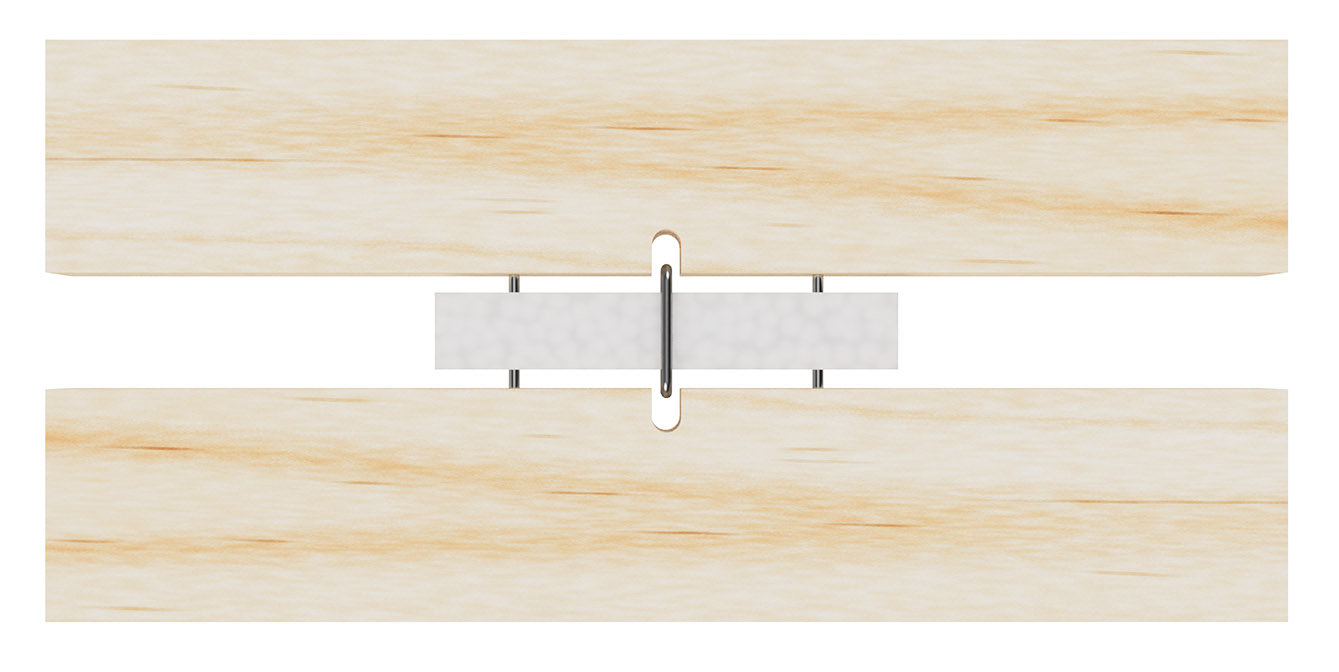
Construction is very simple. As shown in the blueprints, hammer two finishing nails about 2 inches apart into one of the boards. Drill matching holes in the other board to push the head side of the nail into (make those holes a little bit smaller than the head, so it fits tightly). The 0.5″x3″ samples rest atop these nails as shown in the pictures.
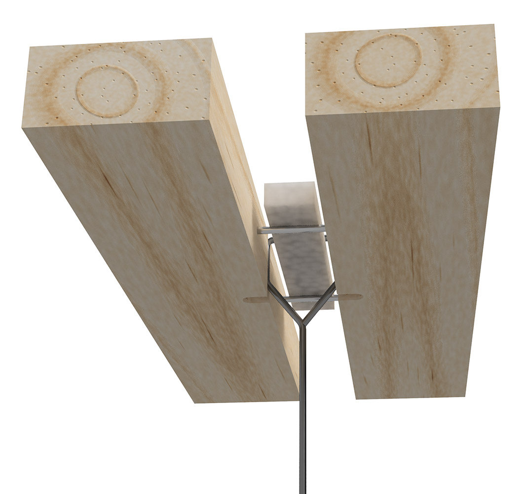
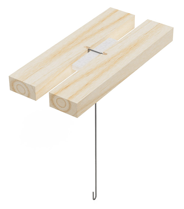
Bend a hook from a metal coat hanger or similar wire to loop around the sample. Make loop around the sample should be flat on each side (i.e., a square-ish loop rather than round) so that the weight is applied evenly across the sample, not merely at the edges. Bend the bottom into a hook onto which you can hang a bucket or bag. The exact length of the two pieces of wood will be determined by how large the gap is. Make sure there is plenty of overhang, as shown in the photo. You can clamp the jig to the table, if you find it is moving around too much.
Additional renders and photos of the jig’s components and testing in action are shown below (click to enlarge):


Running the Test
Slowly and carefully add weight into the bucket/bag. Gently place the weights in the bottom, do not drop them in. Use whatever weights you want, be it sand, marbles, coins, etc. Add weight more slowly for weaker materials (like foams), which are likely to fail with less weight than more sturdy materials (such as hardboard).
Impact Testing — Falling Dart or Ball
A falling dart (or ball) impact test is used to measure the resistance of a material when a force is applied at high speeds. If using a dart, the force applied is concentrated at a very small point, whereas with a ball it is more spread out.

Supplies
- One 8 inch piece of 1×2 wood
- One 35 inch piece of 1×2 wood
- 1x Angle bracket
- Screws for the angle bracket
- Long cardboard tube (such as from wrapping paper)
- Tape, string, or zip ties
- 1x Clamp for holding jig to table
- 1x Dart and/or large ball bearing
Construction
Very simple in concept, this jig is essentially just a tube strapped to a support. You could even forgo building a jig entirely and strap the tube to a chair or table leg! The only firm requirement is that the dart or ball can fall freely through the tube.
However you decide to make it, the end of the tube should be positioned 1 inch plus the length of the dart (or diameter of the ball) above the sample. The cardboard tubes from wrapping paper rolls are perfect for this. The tube can be attached by taping it to support, using zip ties, string, rubber bands, etc. Clamp the base of the jig to the table to prevent wobbling or tipping.
For the projectiles, commercial throwing darts with metal tips work well. In the photo below, the orange one has had its fins trimmed to better fit into the tube. (These two darts weighed 12-13 grams.) The balls we use, shown below, are 67 gram steel ball bearings, with roughly a 1 inch diameter.
There are many ways to make a “dart” if you don’t have a commercial one. The one shown below was made from a complementary hotel lotion bottle. A hole was drilled in the end of a dowel big enough to insert a finishing nail. Drill a hole in the bottle cap. Wrap masking tape around the nail, then screw the nuts onto the nail. Cut the dowel do that it touches the bottom of the cap when screwed on. Wrap paper towel around the dowel so that it won’t move inside the bottle. (This dart weighed 37 grams.)
Additional renders of the jig are shown below (click to enlarge):

Running the Test
A 1″x1″ sample is placed atop a piece of scrap wood or cardboard and a dart (or ball) is dropped down the tube (starting level with the top). For a dart, did it pierce entirely through the sample? If not, how deeply did it indent? Did the material around the hole bent or is it a clean punch? For a ball, what kind of impact did it leave on the sample? What extent? Is the damage permanent or did it elastically spring back into shape?
Impact Testing — Pendulum
This variation of impact testing, using a pendulum, is modeled after the Charpy or Izod standard impact tests, used to measure a material’s impact resistance. This is a more complex testing jig, but kids really like running these experiments.
Supplies
- Two each of ~32-33 inch and 6 inch pieces of 1×2 wood
- One each of 28, 4.75, 3.25, and ~2 inch pieces of 1×2 wood
- One 5.5 inch wooden dowel, 1/4 inch diameter
- 2x angle brackets
- Enough screws for the angle brackets
- 4x for the sample clamp + 1 for weight support + 2-3 for attaching angle guide
- Can or bag for holding weight
- 4x washers (large enough to fit the dowel through it)
- 4x large paper clips, suitable length of wire, or thin rod
- 1x Eye hook (large enough to fit the dowel through it)
- ~18×30 inch piece of cardboard, chipboard, or similar stiff material for angle guide
- 1x clamp for holding jig to table
Construction
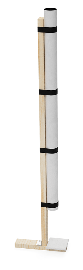
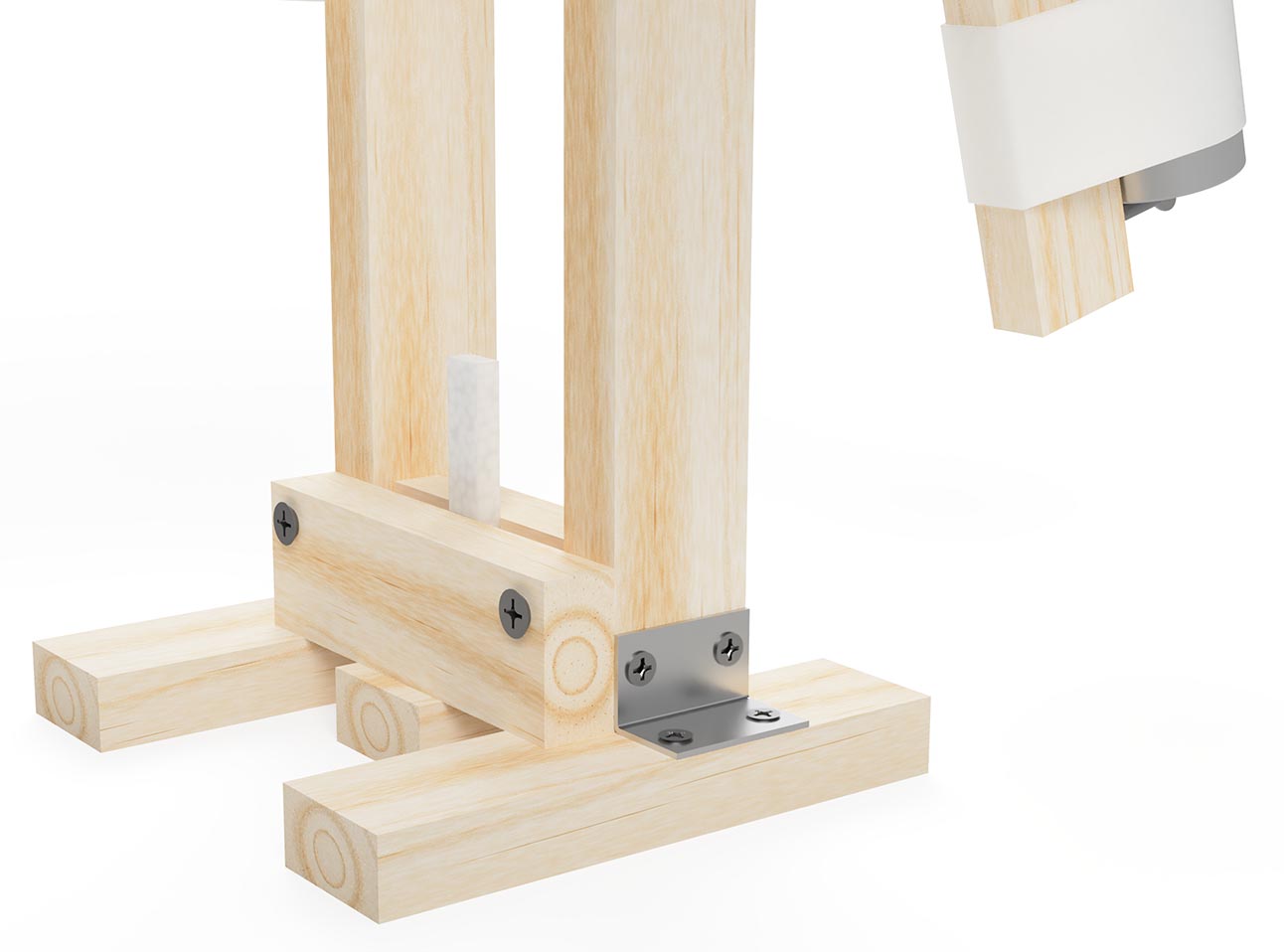
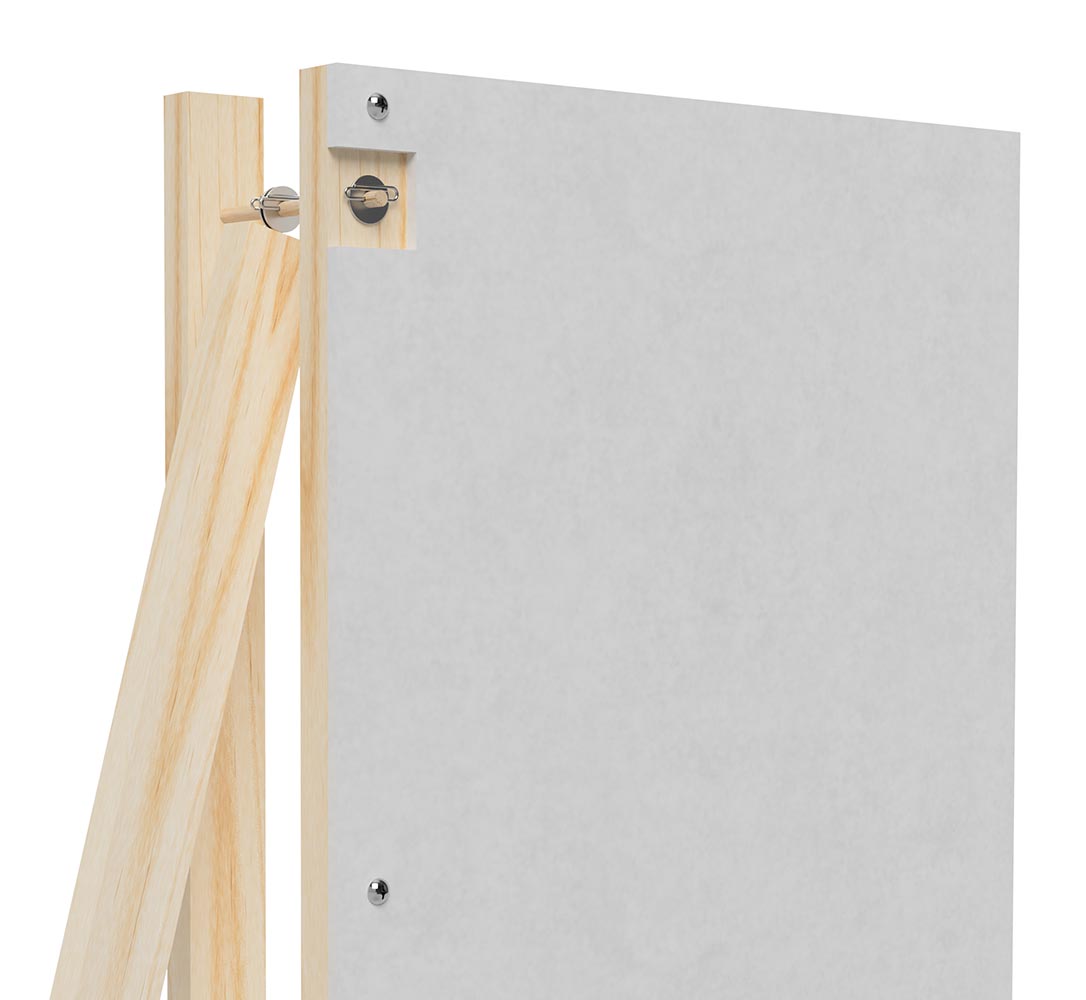
The size of your dowel, washers, and eye hook can vary, as long as they fit together nicely. Make sure your dowel is thick enough that it won’t bend under the weight of the swinging arm. As shown in the blueprints and close-up pictures, drill four small holes in the dowel and insert paperclips (or other wire) into them, to keep the components from sliding along the dowel (and the dowel itself from sliding out of the supports). You can also replace the wooden dowel with a threaded metal rod, and use (wing)nuts to hold things in place. It’s more expensive, but if you already have the components then go for it!
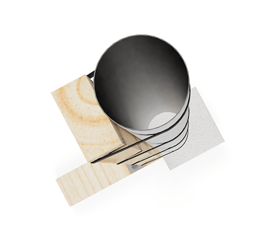
As seen in the closeups below, if you’re using a can to hold weight, adding a screw below it will help prevent it from slipping down (and off!) the arm with repeated swings. You can fill the can with your heavy items of choice, stuffing some cloth or paper towel in there to help keep things from shifting around during the swing.
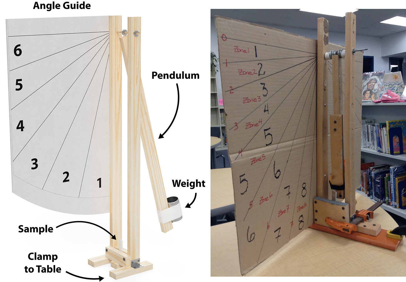
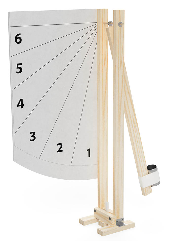
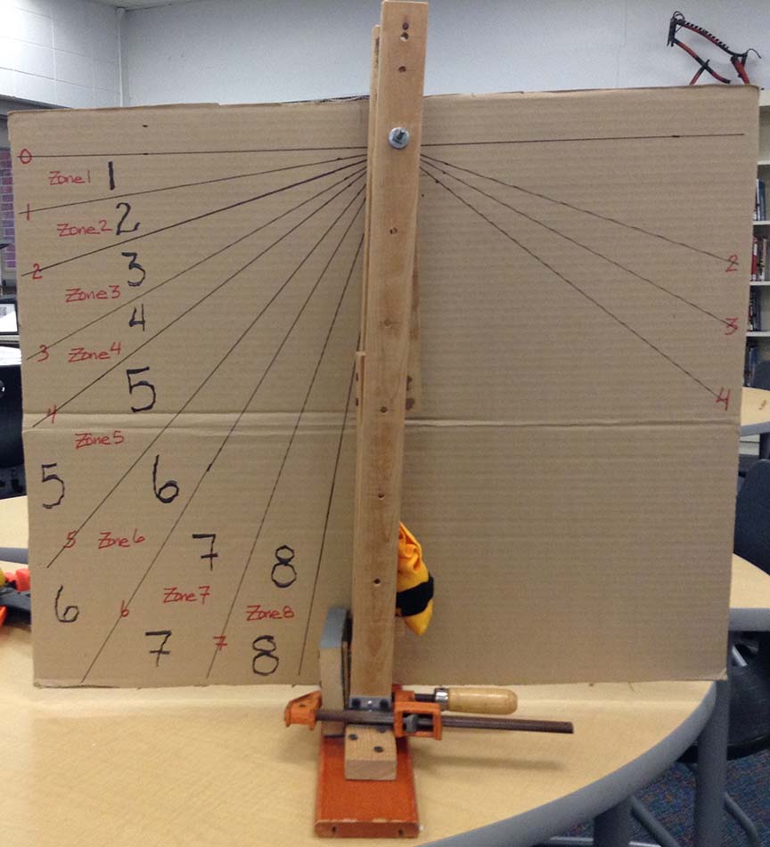
Draw the angle guide on a piece of chipboard or cardboard. It can be screwed or tacked into the support leg. The origin of the lines should be at the dowel. Six to nine zones (every 15 or 10 degrees, respectively) is a good number. Without a camera, or moving indicator arm, any finer angular resolution is impractical.
Clamp the jig to the table to prevent it from moving or tipping over during the tests.
Additional renders and photos of the jig are shown below (click to enlarge):


Running the Test
Insert a 3″x0.5″ sample into the jig as shown. Half of the sample should be exposed, for the swing arm to impact. To loosen and tighten the sample holder, use the two screws in the back (indicated in the blueprints), the ones facing the swing arm. Tighten it just enough to keep the sample from moving around, but not so tight as to deform the sample.
Pull the arm back until it is horizontal and then release it. Have a student watching the angle guide so that if the sample bends or breaks such that the arm keeps swinging after impact, the furthest zone reached can be noted.
How did the sample respond to the impact? Did it bend? Did it break? If it bent, was it permanently deformed or did it spring back to its original shape? If it broke, what kind of break was it? Clean and sharp, jagged and splintery, or stretched out? If the arm kept swinging after impact, how high did it reach? 15°, 30°, etc (Zone 1, 2, …)?
How did your testing go? Did you make any modifications, or come up with an improved design? Was any thing unclear in these instructions? Let us, we’d love to hear from you! Drop us a note or leave a comment!

0 Comments